Post Overview:
This post details the wiring of the main internal components and the first power up of the full system.Introduction:
This post details the (power) wiring of the main internal components including the AMP, JAMMA and speakers. The post then goes onto describe the initial system power up. Thus, this blog entry is split into three sections: extending the power connections options, wiring the amp/speakers/grills and finally wiring the controls/JAMMA.Links to the full photo set for this build stage are also provided, but they contain no context information and thus are best reviewed after reading the blog entry.
The blog entry closes with post-build thoughts and where possible, suggested 'next time' improvement ideas.
Internal Component Wiring- Construction:
Overview/Background: Before we get into the real core of this post, there are a few really important points to mention.Point One: when trimming cables ensure the to-be-cut-off wire strands are caught in your free hand. The biggest risk posed from these miniature horrors is that of shorting out the circuit boards.
 |
| Catch the cut-off strands in your hand. |
Expect damage if they come into connect with a circuit.... they also have a tendency to stick into your skin and under finger nails - nasty little sods.
To avoid these issues, clip off any wire ends into a cupped hand and put the strands into the bin.
Also, vacuum clean the working area at regular intervals and especially if planning to tilt or flip the table.
 |
| Player l, Button 2 & 3 need to work |
Point Two: Hindsight: identifying which wire does what job is very important (and extensively covered below), but it is Critical (but not disastrous) that Player One's switch 2 and 3 ('fire' buttons') are identified and correctly connected. Even if during the early stage of wiring these are temporarily attached to loose/hanging buttons, make sure they are correctly connected - you'll thank me later.
 |
| Double Green = All is good. |
Point Three: Once the JAMMA is wired, powered and happy, you'll get two green lights on the board. One green is for power and one (flashing orange to being, solid green once ready) is for the ROM check. The ROM check is a self test that checks the games (ROMS) are good. Either way no lights, means a very unhappy JAMMA board.
 |
| limited connection space on the PSU |
Firstly the available power connection points and locations were extended (during this optional step). The PSU itself has a limited number connectors and these are all located on the actual PSU. This means that all power cables have to run back to PSU and this in turn creates a bottleneck.
 |
| Extra ground connections |
To counter this bottleneck and to give more connection possibilities, the PSU 'ground' connection point was extended to two locations within the table. One extended ground was run to the cool side of the table.....
 |
| Extra ground and 12V+ feeds near the PSU |
......with the other being positioned on the shelf near the PSU. Both were linked to a terminal block to allow for extra connections. The 12V+ feed was also extended, but only to allow more connections within a terminal block.
 |
| Thin (red) AMP wire. |
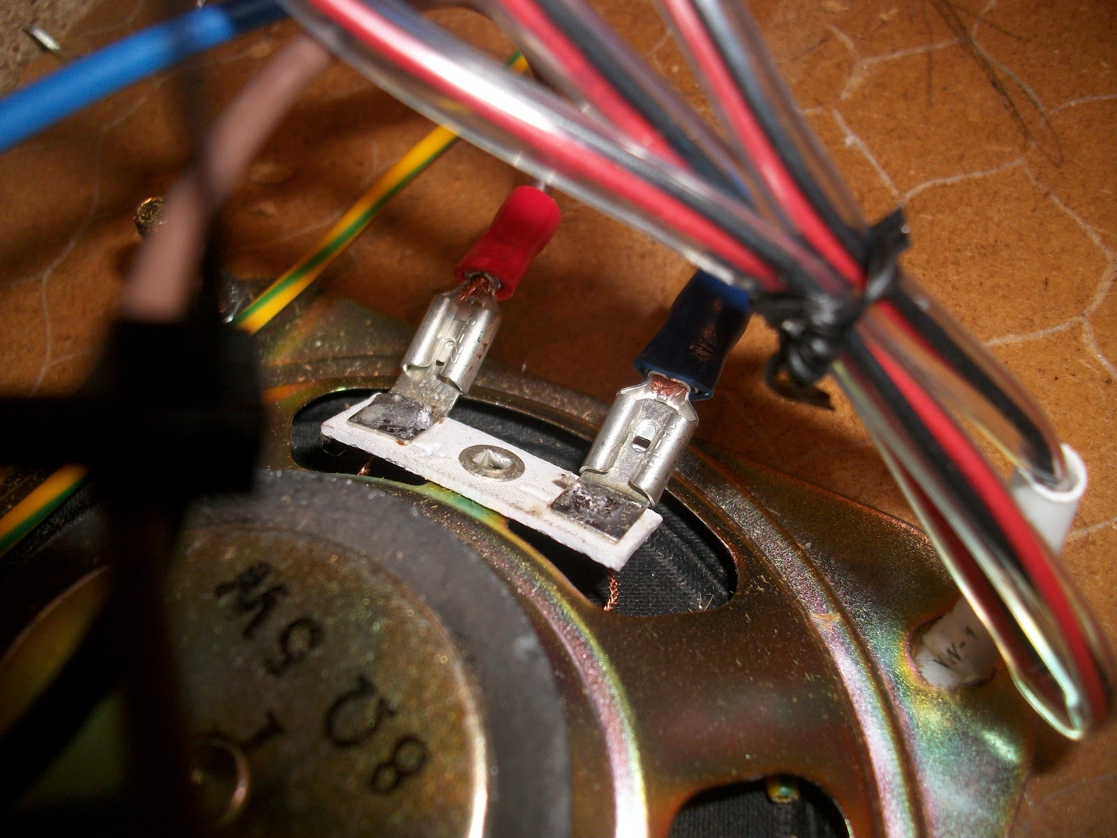 |
| One set of fitted speaker wires. |
 |
| 2nd set of cables - note the plus/minus symbols on the white background |
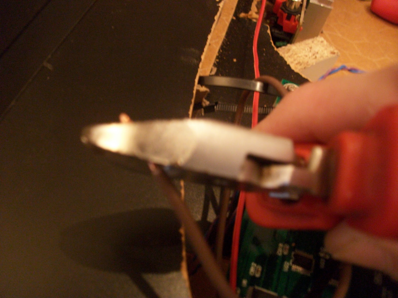
If the female connector is too big, use a pair of pliers to gently squeeze the connector's jaws to a smaller/closed size. DO NOT squeeze the connector while it's connected to the speaker - you'll never get it off again and speaker damage is almost guaranteed.
 |
| Left speaker cables fitted |
One set of fitted speaker cables in the AMP.

Both sets of speaker cables in the AMP.

Standard 'head phone' cable being fitted to the AMP - red to red, white to white......

.... the other end going into the JAMMA.
JAMMA Wiring:
 |
| The JAMMA wiring loom ("WL"), JAMMA Board strip (bottom right) |
Both types of connections (power and control) are contain on this one strip, so when the WL is connected (providing the other end is wired to something) everything gets connected at the same time (this will become important later).
 |
| Loom attached, 'components' side up. |
Thankfully the WL (by design) only plugs onto the JAMMA strip one way up. The wiring instructions talk about a 'component' and 'circuit' side of the WL.
The top of the JAMMA board with all the 'components' is the component side (shown in the photo). The side with mostly solder (the underside of the JAMMA) and no components is the 'circuit' side.
The wiring instructions detail the pin/wire layout, starting from pin/wire 1.... the question is, at which end of the WL/Strip is pin/wire1?
Luckily, the strip itself is helpfully label in Chinese symbols making it a straight forward task for the Chinese speakers in the audience is identify pin/wire 1.
For everyone else, here's what to do.
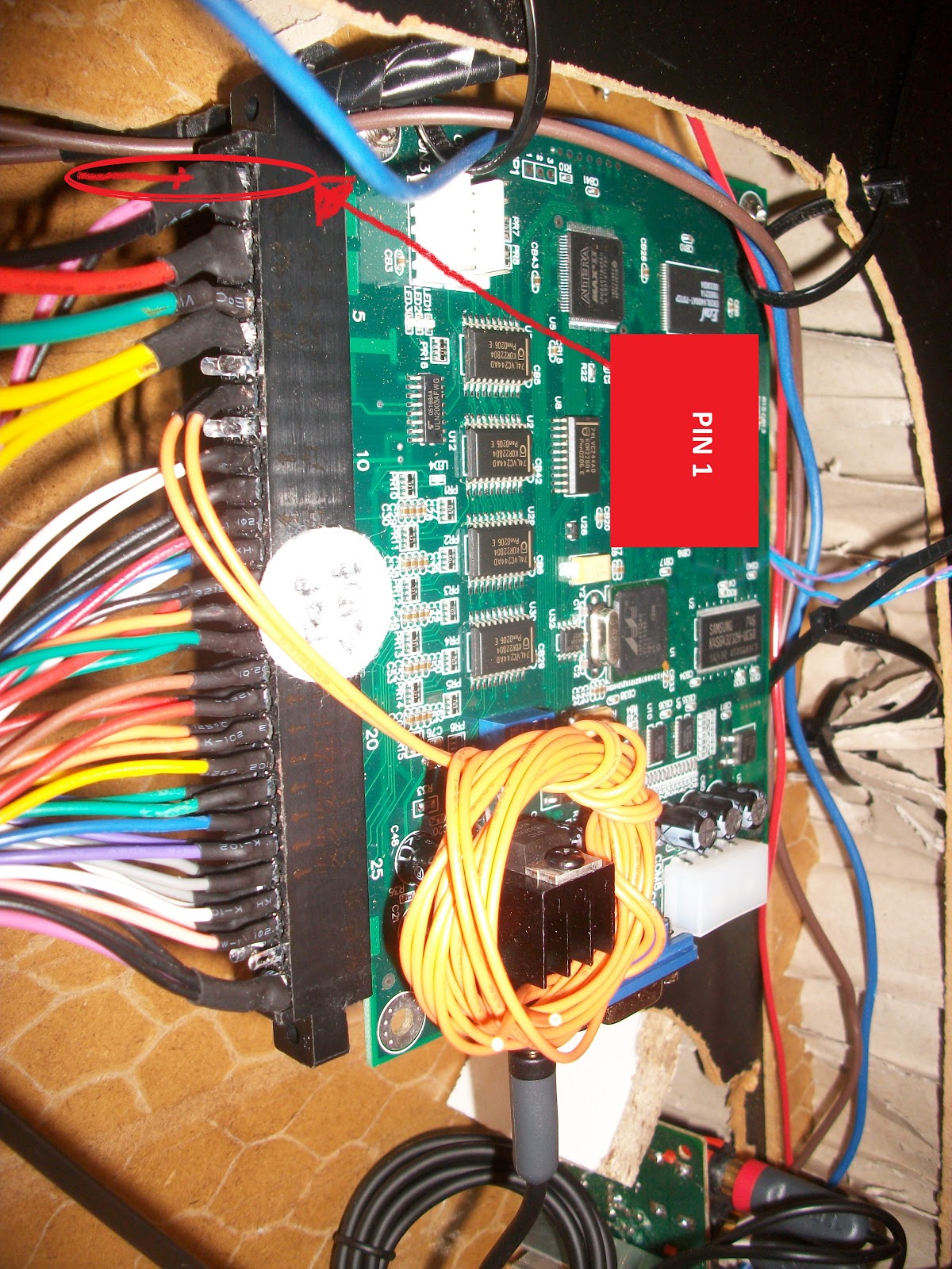 Hold the board (in portrait orientation, component side up) so the VGA monitor connector is facing the floor, or look at the board so the VGA connector is closest to your body.
 This will place the JAMMA connection strip/WL on the left-hand side as you look at it (shown in the photo).
This should mean that pin/wire 1 is located in the top left corner of the board (if it were book, pin/wire one would be on the first line).
This orientation means pin/wire 1 is located (top left) diagonally opposite the standard PC, white molex power connector (bottom right).

To be triple-sure, the power leads for wires 1 thru 3 (black, red, yellow) are thicker than the other leads and have pre-fitted power 'fork' connectors.
 |
| Cross ref the list with the cables. |
This last extra, extra check can be a little miss-leading, as there are additional wires on the WL that aren't documented (e.g. wire 11 is listed as blank, yet a black wire is attached). However, for those wires that are listed, match 'em down the list.
Phew...... right what's next? Let's find all the wires that won't be used.
 |
| Unused wires, find and taped. |
These wires where identified one at a time, by working down the wiring document in tandem with the wiring loom. Non-required wires were curled up and taped to stop circuit shorts.
The required wires where grouped into one big bunch, then grouped into smaller logical bunches: all player one, player two, control buttons, etc. Once this was done (and it took awhile) the actual connecting began.
 <interlude>
The work described so far had taken about four hours - identifying pin one and the wires in general took the bulk of the time. It wasn't really hard work, it was just time consuming. However, with the above information and the experience gained, I guess repeating the exercise would take about 1.5 hours max.
<interlude over>
 |
| #15 Test Switch, the first wire to be connected. |
The first connected wire was number 15, the 'Test Switch". Note the final connection/s, this will be important later.
 |
| Holding Player One's control wires. |
One set of control wires runs to player one and other to player two.
These wires are the same colours for both players, but Player One's wires runs from the component side of the strip (top).........
 |
| Player Two's control wires. |
...... while player two's run from the bottom.

Hole drilled to feed the wire out of the table into the control panel.

A plastic IKEA cable tidy was fed into the table and....

.....secured into place within the table. The grouped wires were routed into the control panels, ready for connection.
|
| Inside the control panel |
The connections on some of the buttons were tight, but seemingly not shorting out.
 |
| Which one is up? |
Also, the physical joysticks switches were placed such that either of two actual switches might be the correct switch for any one wire.
For example, while trying to connect the 'down' wire, the correct switch might have been the one on the bottom or the one on the left. To begin, they were just connected in the most logical fashion.
 |
| Looking Good. |
A finally double check that all the cables are connected ok.... The cable were then hidden in the remainder of the IKEA cable tidy and zip tied into place.
POWER TIME
Finally, after over six hours work on this stage (alone), the power is connected and........nothing! |
| It no worky. |
Nothing Happens!!!
Ok something. A small little hope that all isn't for nothing. The speaker grills light up.
It's small consolation as the board is dead or at least no green lights.... but, but wait.......no green lights simply means no power to the board, right?
<Phhhhhewwwww> Easy fix!
.......but, wait. There IS power to the board! I can see the connected power cables with my own eyes..... faulty board?.....or......did I overload and blow the board??
Did I screw-up the ONE thing that really spells costly disaster for the whole project???
<super duper fuper rooped McFookingDuper sad face!>
Stage Review/'Next Time' Thoughts:
Wow, where to start. I didn't expect the wiring to be completely correct from the very first power on. What I did expect was 'something' from the board, but let's cover that on another post. The items marked above as 'will be important later' will be referenced in the upcoming debugging post.Monitor lead: with hindsight, the internal monitor lead could have been longer {original post has been updated}. This would have allowed it to be connected to the monitor while the screen was sat on the floor, which in turn, would have been better for general access.
Connection blocks: A nice internal touch, but not entirely needed. That said, I wouldn't change this feature for the bottleneck reasons detailed above.
Zip ties: same mistake as always - don't tighten them until everything is working/done. I was forced to remove most of them while debugging the wiring/board problems.
 |
| Too short power leg. |
When the power is connected, the length of the combined cables (male/female power) is too long to fit within the extension leg space. The pre-build answer is to make the leg extension section longer. Post-build, the leg could be extended and the cable re-routed thru the longer section.... or the fitting of a surface mounted female power connector would also solve the problem.
However, because I sick of fannying around with the legs (and control panels) ans just want to play the damm thing, I'm going to cut a small slit into the power leg, so the female connector pops out at a right angle to the leg.... good enough.
Wiring: this took a lot of time and little help could be found via Google/YouTube. There was some basic information, but nothing to really help a beginner. It would appear (based entirely on my own searches) that no-one has produced a comprehensive end-to-end JAMMA wiring tutorial or even guidance documents for any level of competence. Hopefully when this post is refined and converted into a instructables, it will be a start for other people.
Links to photo set:
Similar to build Stage 5 and Stage 6, the photo set for this stage contains more pictures than those in the above blog post.=
=

