Post Overview:
This post covers details of the construction and covering method of the two control panels.Introduction:
This post details the creation of the two control panels ("CPs") which will house the buttons and joysticks. As noted during the shopping list post, the wood used for their construction was sourced from a cheaply purchased "Rundvik" TV/video/dvd cabinet from IKEA.The post is split into two areas (with some minor overlap): the actual construction and the covering of the CPs.
Links to the full photo set for this build stage are also provided, but they contain no context information and thus are best reviewed after reading the blog entry.
The blog entry closes with post-build thoughts and where possible, suggested 'next time' improvement ideas.
Control Panels - Construction:
Overview/Background: Having now built the the control panels it's possible to elaborate on the required wood sizes. Each of the two constructed CPs measures W 18cm x L 23 cm x D 14.5 cm. |
| Left over wood |
The Rundvik cabinet also comprised more than enough wood for this build stage and several large pieces were left over for another project.

The Rundvik cabinet was partially dismantled, so that the lower and middle shelves were left intact to form a partial box.
 The extra side flaps (the 'sticky-up-bit, prev photo) and the other non-flush areas were cut flush to complete the partial box. The controls were also roughly drawn-on....
 By the time the CP was complete, the control area shown in the photo would become the front (not the top) of the CP. If the controls had remained in the shown location, the CP would have been too wide and stuck out from the main table body further than needed.

The box shape was finalised.

Here we can see some of the prebuilt Rundvik strengthening pieces; the CP was cut as close to the pegs as felt safe.
 |
| That's no box! |
Those reading this post that are geometrically minded will have spotted that the pieces doesn't create an enclosed space. Well Spotted!
The bottom of the CP is currently open as this area isn't normally visible. While no final decision has been made, this open-area is the current design; a lower section might get added later.
 |
| Unbevelled |
Here we see the rough, unbevelled control panel.....
 |
| Bevelled |
...... and post-bevel.
It's worth noting that the CPs will be wrapped in sticky backed plastic, so the fact they are a little ugly / out of shape at this stage doesn't matter.......at least that was the plan.
 |
| wrapping the CP |
Covering the CP in plastic begins.....
 |
| wrapping the CP |
 |
| wrapping the CP |

The final product....... and it looks crap. We'll address and fix the crapness later, but for now, will carry on with the construction.......
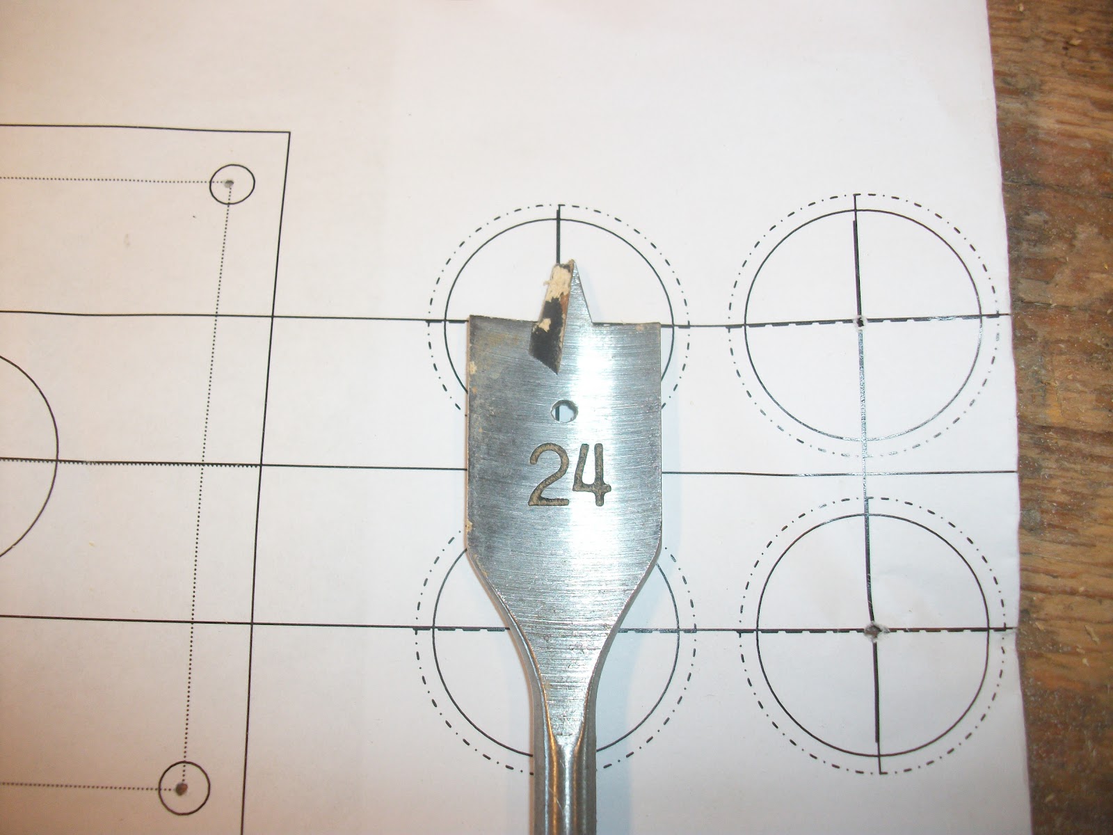
Time for some control button holes, but the largest flat bit in the tool-box is too small. D'oh!

Plan B: see what's lying around the workshop.... and bingo! When tightening screw, do ensure you don't slip onto the cutting edge.... it hurts :(
NOTE: Ensure that the holes are large enough to fit the buttons: 26.5 is a good size.
 |
| Update Photo: Add side button hole |
{UPDATE: POST BUILD}
Add an extra hole, on the side of each controller for the start buttons.

Holes drilled...... but the CPs are just too ugly for words, action will soon be required.

CP fitted to the main table (layer one) and full ugliness of the CP becomes clear, My Eyes!

The fitted catch bolts are used to keep the CPs in a playing position.

Jump forward a little, here's a sneak preview of the table with the ugly CPs fitted. The white section within the table (layer two) are strengthening pieces added to support the catch bolts.
<interlude>
Before moving onto the re-covering of the CPs, a few words are required (more details will be put in the below 'stage review' section). As can be seen, the original covering looked really bad, so a decision was taken to remove the plastic and spray paint them instead..... as will see, this introduced other asthetic issues.
<interlude over>

Off with the plastic......
 |
| Out of shape |
These areas were never meant to have been seen, as they were going to be covered in plastic. With the plasitc removed, they need smoothing out......
 |
| Restyled |
...... now that's better.

Both CPs stripped down ready for spraying - the original white plastic "won't make a difference".

CP in the spray booth (an old cardboard box)

Remember that original white plastic that "won't make a difference", it made a difference..
{UPDATE}
 |
| Recap photo |
This is the 'finished' control panel from the above build work. It looks really bad.

Re-stripped down.

Re-bevelled.

Re-sprayed; paint still wet.

Finished and looking much better than the original 'finished' item; scroll up and take a look at the difference - it was well worth the extra work.
Stage Review/'Next Time' Thoughts:
Unlike stage one and stage two there are several design changes to consider for this third stage.Firstly, the Rundvik/wood used for construction. With hindsight, it would have been much easier to have just bought some wood, cut it to an even size and make the CPs from scratch instead of trying to keep the box shape integrity of the existing cabinet. The time saved buying the cabinet from Ikea "while I was there" was more than lost in having to work around the existing construction.
Secondly, the plastic wrapping: a good idea that just didn't work in practice. With so many angles on the CP to consider the plastic just didn't sit right. Spending more time/care (I doubt would have helped) as even where the seams weren't visible, the effect was poor..... it just looked really cheap (which it was, but that's not the point).
Thirdly, the CP design: the CPs were built prior to the button / joysticks arriving, so thus far it's not know if they could have been built to a smaller size. The bevelling effect on the front and sides of the CP ought to be evened out....
Lastly, the painted CPs: they look better than the plastic wrapped version, but they still aren't great. They really need re-sanding and re-spraying....
Links to photo set:
The photo set for this stage contains many more extra pictures than the above post.=
=