Post Overview:
This post details the wiring of the main power inlet.Introduction:
This post details the method used to install the main power, that will be used to feed the JAMMA power supply unit ("PSU") and monitor. The internal (12v / 5v) wiring will be covered in another post.Links to the full photo set for this build stage are also provided, but they contain no context information and thus are best reviewed after reading the blog entry.
The blog entry closes with post-build thoughts and where possible, suggested 'next time' improvement ideas.
Main Power Installation - Construction:
Overview/Background: There is only one incoming power lead (routed thru the power leg), yet the table will need two 240 volts feeds - one for the monitor and one JAMMA PSU. The JAMMA PSU will be used to feed a host of internal components that run on either a 5v or a 12v feed.Electricity is dangerous, thus connections and wire-ends need to be secure, covered and where possible, placed away from other components. There is also the heat factor of the PSU - lots of heat is generated and we need to get rid of it.
 |
| The white round juction box will house the spliced cables. |
To keep the power connections out of the way, they will be place inside a plastic junction box.
The 'coolest' side of the PSU (i.e. the circuit board side with the solder) is placed on the bottom of the table. This allows the heat from the hot side (i.e. where all the hot internal PSU components are sat) to rise.
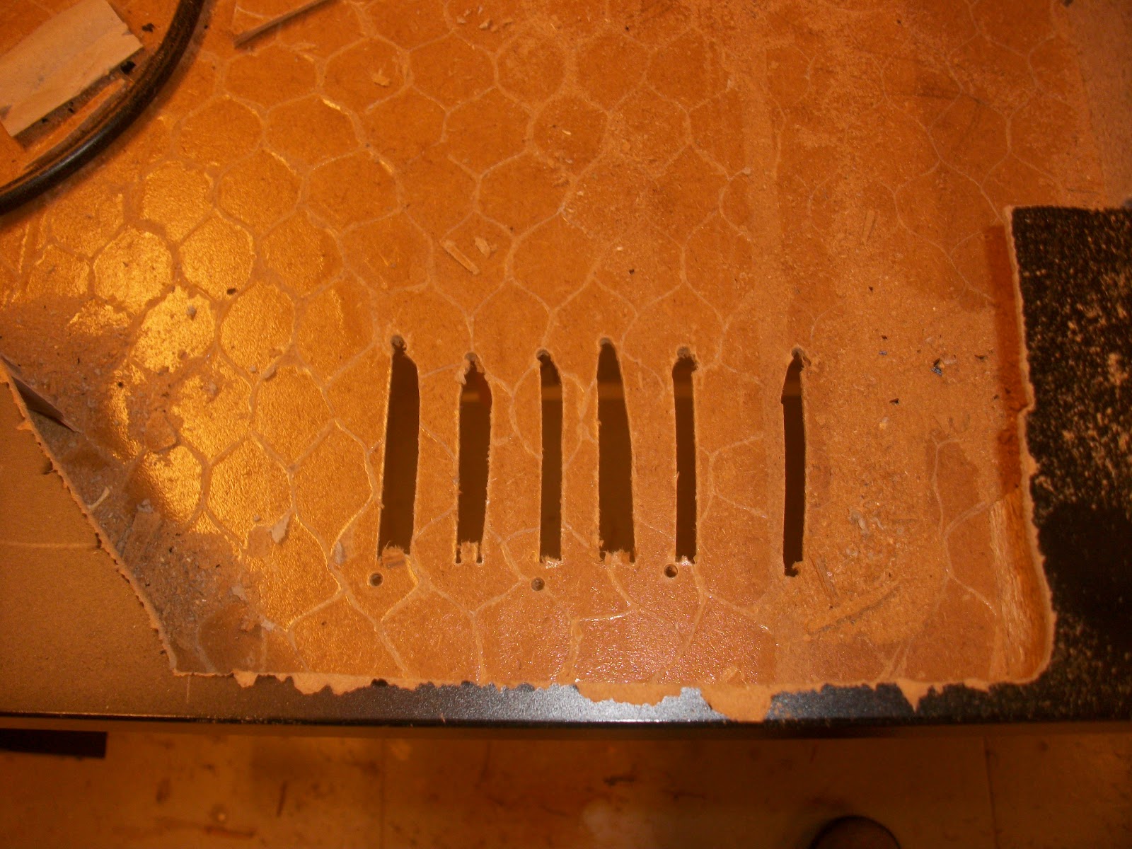
Even though the cool side is on the bottom of the table, heat still need to escape from the main table body. To allow the cool-side heat to escape, some slits have been created under the PSUs final location.... yes they could have been better looking, but no-one (under normal operations) is going to see them.

To allow access to the PSU outlet points, some of the shelf has been removed. Note: the shelf has been cut at an angle so that the 5V and 12V outlets are easy to access and the 'dangerous' 240v area is more covered.
 |
| Incoming main power |
Here we see the incoming power leg cable; knotted to stop pull thru problems.

Incoming power cable, fed into the juction box. Its been coiled, inside the junction box, to allow for more cable to be used (if needed).
 |
| The monitor lead |
<interlude over>

Cable stripping time and a little tip.
If you strip the cable far enough back, and are able to leave the insulation on the ends of the bare wires, the insulation can be used to roll (in one direction, between the thumb and forefinger) and tighten the wire strands, ready for joining together.

It isn't girls hair and we aren't looking for cornrows: this is how you DO NOT join cables together.
Instead, get all (three) strands of the same colour together, cut them to the same length and roll all (three) together at the same time. If you've got more than three strands, use a terminal block.
 |
| Two red screw crimps |
I also taped the screw crimps to be extra safe. The photo shows two completed connections (the two red 'screw crimps' items) with just the earth wires left to connect.

Main power inlet done.......

..... and hidden away.

The JAMMA PSU is next: here we can see the cables have been stripped (as described above), fed thru and doubled backed within the PSU terminal block. The extra, doubled back insulation/wire was cut away and.......

...taped up for extra safety. The earth wire was left longer and exposed because, the earth is our friend :)

The end result: a long enough monitor power lead, a coiled PSU power feed and hidden cable connections. Build Stage Complete.
Stage Review/'Next Time' Thoughts:
Like stage 5, this build stage went well - but there wasn't too much that could go wrong (maybe just curring the wires too short). The yellow and black tape on top to the junction box is (hopefully) only in place until I can find the real box top. Other than that, there isn't too much more to say about this build stage.Links to photo set:
Similar to build stage 3 and stage 4, the photo set for this stage contains more pictures than those in the above blog post.=
=