Post Overview:
This post covers details of the Power Leg ("PL") and its method of construction.Introduction:
This post details the creation of the Power Leg ("PL"). The PL will be used to route standard 240V power to the JAMMA power supply unit and the monitor. As the standard legs are hollow, a hidden cable will be run thru this leg into the main body of the table. The leg shown in the below photos has already been extended (as part of Stage One, details here), so this post just covers the creation of the PL.Links to the full photo set for this build stage are also provided, but they contain no context information and thus are best reviewed after reading the blog entry.
The blog entry closes with post-build thoughts and where possible, suggested 'next time' improvement ideas.
Power Leg:
Overview/Background: The background design theory is that the planned power cable's position (inside the leg) ought to help with keeping the table looking as normal as possible (part of the overall design goals) and minimise kick/knock-out problems; were the power cable gets inadvertently knocked or kicked out during game play.
 |
| Power Leg components |
The power connection will sit inside the leg extension with the cable running thru the top of the leg and into the main body of the table.

To save time, the wood drill bit was set at its max length, thus the double-ended screw didn't need removing......
 |
| Lining up the holes |
To ensure the holes lined-up the drill bit was tapped into place while the two sections were screwed together. This left a small marker hole in the bottom of the standard leg. The drill bit was then pulled out, the leg extension unscrewed and the marked hole drilled.
 This picure shows the top of the standard leg. The foreground (top) hole was drilled in the same corner as the bottom hole; no measurements were made as these two holes don't have to completely line-up as the cable will sit loose inside the leg. Additionally, two holes can be seen thru the foreground hole. The lower hole (nearest thumb) is the newly created hole (see above), the other hole is the standard pre-drilled hole used to connect the leg extension via the (other) double-ended screw.
 |
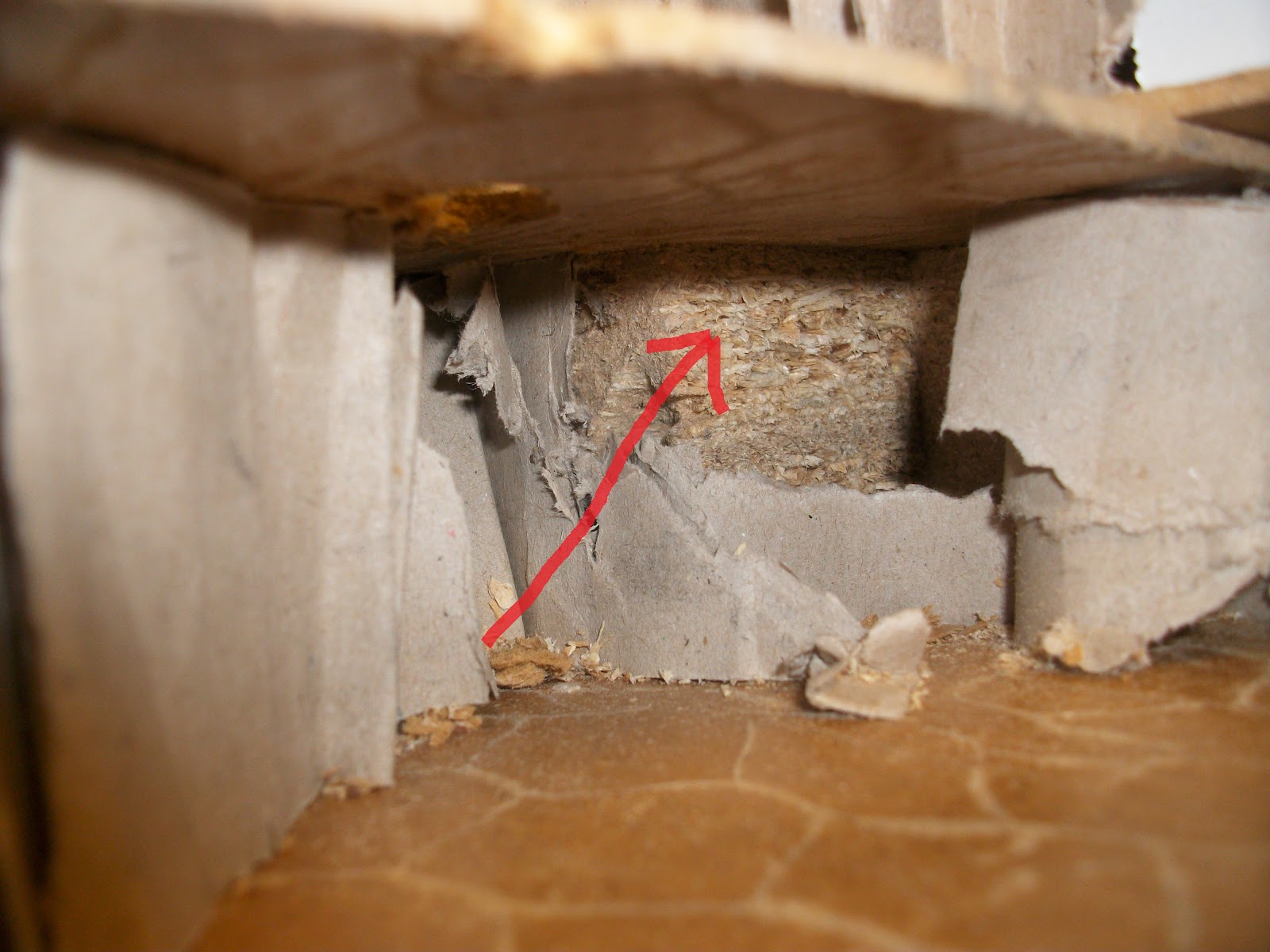
| Red lines show the guess'timation location of the support piece |
The table corner has a solid wood piece used for supporting leg. Hence the power hole has been drilled at an angle in an attempt to avoid the block. Hopefully the cable will go thru......

Power lead sitting inside the leg extension, which has had a small notch cutout to allow for the incoming power connection.

The other end of the cable needs preparing to feed thru the holes. The cable will be taped to a wire coat hanger (an old trick) and fed thru the holes into the main body of the table. First the outside black insulation is removed.

To ensure smoother passage thru the holes, the inner cable strands are cut into differing lengths ready for taping. This will creates a tapered effect, were the first part of the cable entering the hole is the thinest (i.e. just the earth wire + coat hanger) with the cable/coat hanger getting progressively thicker.
 |
| Green: travel direction, Red: taping direction |
Also, tape away from the direction of travel to reduce snags..... in the picture, the coat hanger will be following the direction of the green arrow. Hence, the tape is applied in the opposite direction (following the red arrow). This adds to the tapering effect and aids smooth passage thru the holes.
 |
| Resized to 10mm |
Whilst orginal holes (6mm) were fine for just the cable, the combined thickness of the cable, wire coat hanger and tape was too much, so the holes were redrilled using a 10mm wood bit.
Inside the main table body, the cable will emerge in this area....... hopefully.
 |
| Finally |
<much time passes> After fishing for some time, the coat hanger finally appears thru the top of the leg.

Keeping light pressure on the coat hanger, the leg was slowly screwed into place. The pressure caused the coat hanger to pop into the hole (once per revolution), so it was left just sticking out a little bit until the final tightening turn. Then it was pushed into the main table body hole.
 |
| All done for this stage |
Cable thru the legs and out into the main table body; a completed Power Leg.
Stage Review/'Next Time' Thoughts:
This build stage went ok (like stage one) and at this point I wouldn't change the design. The pushing / fishing of the power cable thru the leg into the main table body took an unexpectedly long time (around 15/20mins). It was a fiddly job, exasperated by having to pull the coat hanger out to widen to holes to 10mm. The corner area was also really tight for space, which made it difficult to grip the coat hanger and drag it into place.As an after thought, it's come to mind that additional power will be required inside the table; power will be required for the JAMMA PSU and for the (yet-to-be-installed) monitor. Current thoughts are either to split the incoming cable (to feed the two items) or just install a junction box.
Links to photo set:
==