Wednesday, January 30, 2013

MAME Table: Recap, Costs and What Next {Stage 10}

Post Overview:


This post gived a project recap, covers the total project costs and 'what happens next' details.


Introduction:

It all starts here.
This final post in this series covers three core topics: a recap, project costs and next step details. The recap section looks at why this project was originally conducted and the different build stages, before defining project success factors.

The blog then examines total project costs from several points of view.  This is followed by a  'what happens next section' covering final improvements and another build project.

The blog finishes with some final thoughts.


Background and Recap

Background

This project was started to gain experience, skills and iron out the kinks of any future builds.  The plan was to build this JAMMA based table, in preparation for building a MAME box within the same concept table.  The project itself was started with an idea but no real plan.  I knew roughly how I wanted the final table to look, but I didn't know specifically how I was going to get there.  I think the original idea spawned after seeing this post and as noted in the shopping list post, I did spend some time looking for a glass top table.  In the end, the original design wasn't what I had in my mind's eye and thus we started this build journey.

Recap

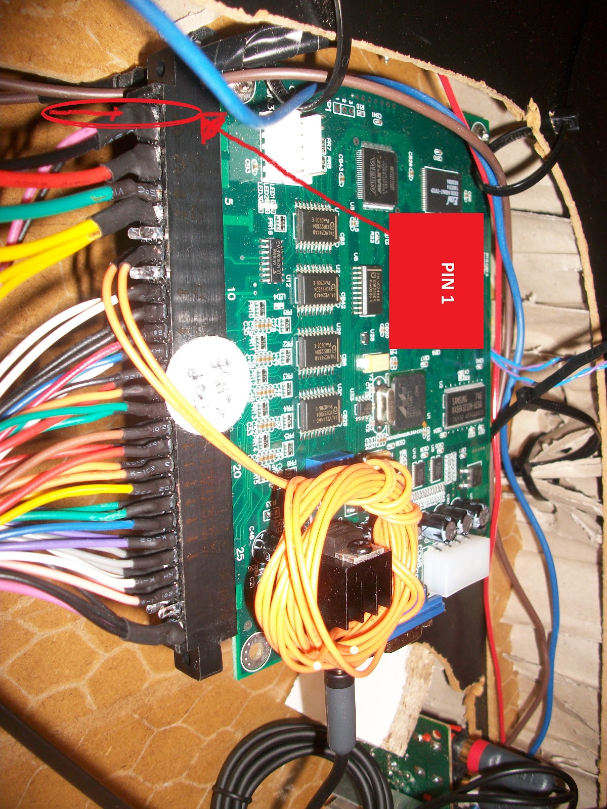
The build itself involved extending the IKEA Table legs and runing power into the main table. The cotrol panels were built, refined and changed one last time. The table itself was prepared, wired and the monitor fitted. Finally, the base wiring was fitted, then the JAMMA with this being followed by some trouble shooting.

Underside - Night Time
Total build time wasn't really a pre-build factor, but towards the end of the project I just wanted to get down to playing.  This meant that tasks that would have been tackled with more care and attention were just attended to in the quickest possible fashion. 

Could this project have been completed in a short-time frame? Yes, and if I was to repeat this build exercise then I could without doubt complete the task quicker than last time and at a (slightly) reduced cost [see 'Costs' below]. 

 
It's become clear during this build, that the table structure for the planned future system would be ok, but the control panels would require a redesign.  This is covered below in the 'what happens next' section.  


Project (build) Time

It took some time
The project task that without doubt took the most time was writing this blog.
 
As a rough estimate, I'd say that it took at least three times as long to write this blog than actually build the table. 

So why did I write it?  What did I get out of it?  Peoples interest and positive comments helped push me into getting things done.  Also in the past, I'd used the Instructables site for many things, but it does relies on people contributing.  I wanted to give back to the community and thus, these blog entries will be stripped, cleaned-up and re-formatted into an Instructable.


Success?

Was the project successful? The design objectives were covered in this original post and the design framework has been followed and thus, from this perspective the project has been successful.  The final result ticks all the boxes of the original plan, so again from that perspective the project can also be deemed a success. Costs weren't factored into the build, but the total was more expensive than originally expected.....


COSTS:


You scrolled-straight to this section didn't you? That's ok.  You're scanning for a final price aren't you?  Well, you're gonna need to start reading now...... why not even get in the mood and read this blog entry from the top ;)

How Much?
Unfortunately for those looking for a quick answer the high-level response is, "it depends".  There are at least five different perspectives and thus, several ways to answer the cost question.

 
"shopping list  Versus  in-stock": Some items I had to buy specifically for the build (e.g. the JAMMA board, PSU, AMP) but some items I already owned (had 'in stock').  Examples would be the electric drill and jigsaw.  I couldn't have built the table without these pre-owned items, so should we include only the specific missing items when calculating the costs   or  the total costs to replicate my current setup for the new starter?......before you answer, consider.......

"reusable  Versus  specific": Some of the items I purchased to build the table are items that will and can be reused at a future date.  I'm think about drill bits, saw bladed, wiring items, crimp kit, screw/bolt sets.... these are items that were purchased with the table build in mind, but are reusable and they will give an on-going return..... should these be included/excluded when calculating the total cost?....... hang-on......

True Costs?
"total receipts Versus  false value items": I've saved every receipt for everything I bought that relates to the build.  However, this flat list also shows items that weren't actually used to complete the build.  Also, I got the monitor, a normally costly component, from a friend for very little money.  Do we factor in its true cost for the prospective builder or only the low price I paid...... bored yet?........

"cost of man hours  Versus  not for sale": When the to-be-built table is for me, my hours are free.  Do we place a value on these hours or are these 'costs' only relevant in a sales situation...... enough?

Ok Ok OK....... let's talk about a true rebuild value. If tomorrow, I had to rebuild the table, MY costs would simply be: specific item costs + reusable/one time use items +some compensation for my hours (if for resale).

So, let's take the sensible approach and assume you've got some basic DIY kit.  The realistic base costs for the specific components including the AMP, Monitor, JAMMA, tables, joystick kit (inc joysticks, buttons and wiring loom), grills, glass, wood, cooling (fans and controller) is four thousand two Swedish crowns and that includes a realistic cost for the monitor.  If we included the reusable items like tools, blades, drill bits, screw/bolt kits you can add another one thousand crowns. 

My hours aren't included in those costs and don't become a factor until a sales situation arises.  It would then depend upon who I was selling to (close friend, friend, friend of friend or stranger).  Mr Stanger can look to add at least another two/three thousand crowns.

A few final thoughts on costs: I didn't budget and having now figured out the totals I'm a little suprised at the final costs.  That said, buying a ready built table would have cost at least double and, won't have included the personal build fun.  Also, if I was building the same table again, I could bring down the cost by cutting and changing a few things.  Either way, I'm ok with the costs even if they are higher than expected.


WHAT HAPPENS NEXT?:


Final improvements


Yeah......Geek Lights!
For me the table is really complete, but there are some small improvements/upgrades that are planned.
 
An external headphone socket will be fitted (to the underside of the table) to allow for headphone to be plugged in without the need to open the table. 
 
Also, some geeky internal blue lighting has been order and will be placed inside the main table for a geek-cool effect when showing the insides. 
 
Also, upgrading of the 60-in-1 board to a 302-in-1 board to allow for more games to be played is also planned (but not yet ordered).


Another build?:


As noted above this was the test preparation build for the real to-be-built MAME box.  However, a redesign would be necessary because of one of the core design objectives of the to-be-built table, specifically the ability to play Karate Champ, Player Vs Player.
 
First, some arcade history: one of the core concepts behind the JAMMA standard was to keep operating costs low for arcade operators.  This was partly achieved (via the JAMMA interface) by making the product differentiator (i.e. the arcade mother board within each cabinet) easy to replace. 
 
Karate Champ - Not popular or standard controls
If you think about it, most arcades cabinets are based on the same fundamentally design/unit - two side-by-side joysticks, some control buttons and a screen sat inside a cabinet.
 
Outwardly, the logos/printed graphics might need changing, but why replace the whole cabinet to get a new game, when only the mother-board needs changing?  It's no different than a Super Nintendo (/Atari 2600); swap out the cartridge and get a new game - you don't buy a whole new console.  Enter the JAMMA interface.

So what has that got to do with redesigning the controls for the planned build? Karate Champ, Player Vs Player.
 
Unfortunately, this personal-must have game is somewhat unique in its control method - one player requires TWO side-by-side joysticks, located near each other to control the in-game character; no buttons are used to play (see picture). 
 
For the arcade owner, this posed a problem as it meant that a dedicated cabinet was require or at least, a dedicated control panel. 
 
Think back. The current project's control panels are located (cocktail style) on opposite side of the table, so whilst it would be possible to swap-in a new control board ('cartridge') via the JAMMA connector, playing the game would be nigh on impossible.... also player vs player would be completely ruled out (four joystick are needed). 
 
Side Note: I've never met anyone else who can actually play this game beyond the level of 'randomly move joystick and see what happens' and this I believe (in part) can be linked back to the dedicated cabinet problem.  The game wasn't that popular with arcade operators because the cabinet couldn't be easily upgraded to accommodate another game, due to having no 'fire' buttons and four joysticks. 
 
Thus, limited availability (I only every saw this game in about two of fifty'ish arcades) and a steep learning curve (at 10p a try) in comparison with similar games (Kung FU Master and Yie Ar Kung-Fu) with button controls, was simply too much for most people. Anyway......

This leaves me in the same position as the arcade owner of old and at the design stage of the future build with a few options:
(1) forget it, it's not really needed and too much trouble,
(2) modify the current table to include another control panel with the right controls,
(3) build another similar table, but have the right control panel or side-by-sides controls.
(4) build a bar-top cabinet with the right controls. 
At this stage I've not decided, but I'm leaning toward option 3 and in fact, I've not even fully decided if I'll even proceed with another build as I'm enjoying the current table so much.
 
So, long story short: maybe another build, maybe not.
 

Closing Statement:


I've really enjoy building this table and I'm really happy with the outcome.  I also hope you've enjoyed reading about it...... anyway, I've gotta go, it's my turn to play..................................


Thursday, January 24, 2013

MAME Table: Debugging and JAMMA Config {Stage 9}


Post Overview:

This post follows on from the previous wiring and first power-on blog entry and covers the debugging and configuration of the JAMMA table.

Introduction:

Following on from the failed first power-on attempt, this post covers the debugging and configuration of the JAMMA table. Thus, it covers the steps taken to debug the problems with the currently 'dead' table before looking at the JAMMA configuration via the onboard menu system.

Links to the full photo set for this build stage are also provided, but they contain no context information and thus are best reviewed after reading the blog entry.

The blog entry closes with post-build thoughts and where possible, suggested 'next time' improvement ideas.

Internal Component Wiring- Construction:

Recap: Where's my lights?
Overview/Background: Following the previous wiring post, the current root problem is that the JAMMA shows no outward signs of activity.   More specifically we ought to have a power light to indicate that the board is receiving power.  Thus the logic flow is: no power light indicates (we think) no power, which means no display, and no display, means no JAMMA configuration. Hence we need to figure out the root cause of the power issues.

Two general principles are employed when debugging (this project): 'known good' and 'bare bones'. 

For me, 'known good' mean using components that we 'know' are 'good and fully working.  For example, if we've got another working fully system, we can swap out components from the working, 'known good' system into the failed system and see what stops/starts working.  This principle provides the baseline that we're dealing with at least something that is working or 'known good'.

The 'bare bones' principles involves disconnecting as many components as possible, until we are left with the 'bare bones' needed to test the current component.  A mixture of known good and unknown-status components can be added, one at a time, until something fails/works  or  we get enough new information to narrow down our search to a specific item.

"Bare Bones" - we only need these to test the power.
The hindrance is that we have nothing that is known good - all components are new, thus untested and we don't have another fully working system.  However, there are several items that aren't needed to test the base functionality and thus we can 'bare bone' the system.  Also, we are getting some output from the PSU (as the speaker grill lights up), so the PSU seems ok. 

Thus, the wiring between the JAMMA and PSU needs investigating and is the most likely source of the problem.

First all the connections were removed from the JAMMA PSU, then just the JAMMA power was re-connected.  Nothing! Dead board and no lights. Ok. Bare bones in mind: we'd ideally just connect the JAMMA power but remember the other post....
""Both types of connections (power and control) are contain on this one strip, so when the WL is connected (providing the other end is wired to something) everything gets connected at the same time (this will become important later)""
 

Known Good: Power source from a PC PSU into the JAMMA
This makes it a little trickier as we can't completely bare bone (i.e have only the to-be-tested-items connected to) the system, so it's not clear if something else (other than the power) is the problem.  However, there is another way to power the JAMMA - via a PC PSU and the white molex connector.

We also have a known good PC PSU. Thus disconnect the JAMMA power cables, in with the PC PSU lead........


It works...... from another power source. Hmmmmmm

...... and bingo! Green lights. We've now got a known good JAMMA board and thus have narrowed down the problem to the JAMMA PSU or cables..... but what the hell is wrong? 


Variable output, white round item, top.


The JAMMA PSU has variable output voltage.


Voltage too low......


Voltage check of the JAMMA PSU gives 4.71Volts, compared with 5.32Volts of the PC PSU power.  Bingo!


...... That's better.
The voltage is too low, so time to turn up the power on the JAMMA PSU.  That done, plug in the JAMMA power again and...... nothing? Hmmmm.
Let's check those voltages again.  Minus 5.32 volts. 

Minus 5.32 volts? Minus? MINUS? Well, well, well, well.

I didn't see this problem for looking.  We've got the wrong connectors.... we need the PLUS 5volts. 


-5Volts (top), PLUS 5V bottom.
A problem so darn obvious my eyes hurt.  To test the wrong connection theory, we can swap the red and black power input cables that lead to the JAMMA - it's risky, if we've made the wrong assumption...... Cable swapped and yeah, there's the problem confirmation.  A school boy error, but thankfully, a school boy fix. Re-cabled to the correct 5V+ and the JAMMA board boots-up a treat.


<interlude>
Why didn't I spot this issue? Primarily and quite simply, I didn't see the minus symbol on the PSU <shoulder shrug>

Secondly, on the JAMMA PSU one 5V outlet is marked 15A (amps), while the other is marked 1A (amp).  These values, I now realise but already knew, aren't what the connections pumps out continuously.  They are instead what the terminals are able to supply if the 'pull' (from the connected components) requires that much humph.

I'm oversimplifying, but think about a standard (UK), wall socket power plug - it has a 13amp fuse. If the 'power' drawn ('load') is more than 13 amps, the fuse blows..... why, even for a second, I mixed-up this distinction must remain in the realms of speculation.
<interlude over>

With the power fixed it's time to get some form of display.  Remember the post information that said......
""it is Critical (but not disastrous) that Player One's switch 2 and 3 ('fire' buttons') are identified and correctly connected [...] make sure they are correctly connected""
.....the reason for this is the JAMMA menu system.  The JAMMA board has a built-in menu system which allows for several options to be configured.  Moving around the menu pages is achieved via control panel buttons.  Moving around on-screen options (within the current menu page) is achieved via the joystick.  Changing a specific option (on/off) is normally achieved via a control panel button.
 
DIP Switches - #4 ON if you want the menus.
If the buttons aren't working, then navigation is impossible (Brief troubleshooting note: press every button and see if anything happens and use the 'known good' approach). 

Either way, it is still possible to access the first menu page as there are two ways to get into the JAMMA menu, (1) Set DIP switch four to ON or (2) hold down one of the test switches (if connected) while applying power to the JAMMA. 

I would recommend option one, because if the switches aren't connected....well, it won't work. 


No common ground lead meant the test switches didn't work


For this build I'd accidentally forgotten to connect the common/ground wire to the test switches (an easy to fix problem).


First page of the JAMMA menus, the test screen and cryptic "S2" message.
Once in the JAMMA menus, the first menu page is the test screen with the slightly cryptic "S2 : Next" message.  The test screen is a full screen, test card output which allows for the monitor to be correctly sized. 

The "S2" relates to switch 2, more specifically, Player One, fire button two (P1 FB2).  Pressing the S2 button ("Switch") moves the on-screen JAMMA menu onto the next menu page.  The S3 button, moves backwards thru the menu pages. 


Button Test, via the 'I/O Test' menu
The S2 button was pressed until the "I/0 Test" menu page appeared - from here the button contacts can be tested. 

When input is detected (by pressing a button, joystick, trackball, coin, etc) the corresponding on-screen item is switched on/off.  We can in the photo that P1 S2 has been switched on and that DIP-2 and DIP-4 are also 'on'.

This enables the different switches to be tested; press/move the controls and see if the items light-up.


And again, I was unlucky on two counts as the S3 button, one of the key menu navigation buttons, was shorted out (not shown).  The soultion: remove the wire, add tape and refit.  Secondly the joystick connections where incorrectly connected.  Soultion, remove all joystick cables, re-add them one at a time, see what lights-up on-screen and move cable to correct location, repeat procedure until everything was correct.

"Mr. Do!" Just begging for one more game.........


With all that work done, the table is operational and 95% complete.


Stage Review/'Next Time' Thoughts:

This stage was all about resolving problems and as such, is all about 'next time' thoughts.  The core issue was that of PSU power - both low voltage and wrong connections. 

Getting into the JAMMA menu via the test buttons wasn't initially possible as the common ground wasn't connected - an easily corrected mistake with the addition of the missing wires and using by using the alternative, 'set pin four on' method.  Once in the menus, navigating was tricky due to the wrongly connected joysticks, but the I/O test screen helped to solve that problem.

Closing thoughts: the problems could have been much worse, with a dead JAMMA board being highest on the nightmare list.  Having worked so long, wanting to get the wiring done in one day, I made mistakes (missing wires/wrong connections) - performing the work in two sessions might have helped.

Last post ahoy: "final touches, costs and total project overview" coming soon.

Links to photo set:

=


=

Tuesday, January 22, 2013

MAME Table: Power-up and Wiring {Stage 8}


Post Overview:

This post details the wiring of the main internal components and the first power up of the full system.

Introduction:

This post details the (power) wiring of the main internal components including the AMP, JAMMA and speakers.  The post then goes onto describe the initial system power up.  Thus, this blog entry is split into three sections: extending the power connections options, wiring the amp/speakers/grills and finally wiring the controls/JAMMA.

Links to the full photo set for this build stage are also provided, but they contain no context information and thus are best reviewed after reading the blog entry.

The blog entry closes with post-build thoughts and where possible, suggested 'next time' improvement ideas.

Internal Component Wiring- Construction:

Overview/Background: Before we get into the real core of this post, there are a few really important points to mention.

Point One: when trimming cables ensure the to-be-cut-off wire strands are caught in your free hand.  The biggest risk posed from these miniature horrors is that of shorting out the circuit boards.  
Catch the cut-off strands in your hand.

Expect damage if they come into connect with a circuit.... they also have a tendency to stick into your skin and under finger nails - nasty little sods.

To avoid these issues, clip off any wire ends into a cupped hand and put the strands into the bin. 

Also, vacuum clean the working area at regular intervals and especially if planning to tilt or flip the table.


Player l, Button 2 & 3 need to work

Point Two: Hindsight: identifying which wire does what job is very important (and extensively covered below), but it is Critical (but not disastrous) that Player One's switch 2 and 3 ('fire' buttons') are identified and correctly connected.  Even if during the early stage of wiring these are temporarily attached to loose/hanging buttons, make sure they are correctly connected - you'll thank me later.


Double Green = All is good.

Point Three: Once the JAMMA is wired, powered and happy, you'll get two green lights on the board.  One green is for power and one (flashing orange to being, solid green once ready) is for the ROM check. The ROM check is a self test that checks the games (ROMS) are good.  Either way no lights, means a very unhappy JAMMA board.


limited connection space on the PSU
Down to business.


Firstly the available power connection points and locations were extended (during this optional step).  The PSU itself has a limited number connectors and these are all located on the actual PSU.  This means that all power cables have to run back to PSU and this in turn creates a bottleneck. 


Extra ground connections

To counter this bottleneck and to give more connection possibilities, the PSU 'ground' connection point was extended to two locations within the table.  One extended ground was run to the cool side of the table.....


Extra ground and 12V+ feeds near the PSU


......with the other being positioned on the shelf near the PSU.  Both were linked to a terminal block to allow for extra connections.  The 12V+ feed was also extended, but only to allow more connections within a terminal block.


Thin (red) AMP wire.
Secondly came the wring of the AMP, speakers and grills.  The two wires (comprising the power lead) that shipped with the AMP were really thin.  Here you can see the (red) AMP wire compared to a standard wire (brown).  This made stripping and fixing the wire difficult as it kept snapping.


One set of fitted speaker wires.
Next, two sets of speaker wires were made - a standard wire was stripped at one end (the end going into the AMP) and a female-spade connector crimped on the other end.  These were connected to the speakers observing the correct '+' and '-' symbols stamped onto the speakers. 


2nd set of cables - note the plus/minus symbols on the white background
A few pointers, the connector on the back of the speaker is easily damaged (read: broken off), but not easily fixed.  Therefore test the spade connecter fits before crimping and when fitting, gently push it into place while supporting the back of the speaker connector.....otherwise expect tears. 

If the female connector is too big, use a pair of pliers to gently squeeze the connector's jaws to a smaller/closed size.  DO NOT squeeze the connector while it's connected to the speaker - you'll never get it off again and speaker damage is almost guaranteed. 


Left speaker cables fitted


One set of fitted speaker cables in the AMP.


Both sets of speaker cables in the AMP.


Standard 'head phone' cable being fitted to the AMP - red to red, white to white......


.... the other end going into the JAMMA.


JAMMA Wiring:


The JAMMA wiring loom ("WL"), JAMMA Board strip (bottom right)
The JAMMA wiring loom ("WL") is a black double sided, female connector with around 60 wires connected.  The WL is used to feed both power and control button information into the JAMMA unit, via the JAMMA unit's circuit board strip. 

Both types of connections (power and control) are contain on this one strip, so when the WL is connected (providing the other end is wired to something) everything gets connected at the same time (this will become important later).


Loom attached, 'components' side up.


Thankfully the WL (by design) only plugs onto the JAMMA strip one way up.  The wiring instructions talk about a 'component' and 'circuit' side of the WL. 

The top of the JAMMA board with all the 'components' is the component side (shown in the photo).  The side with mostly solder (the underside of the JAMMA) and no components is the 'circuit' side. 


The wiring instructions detail the pin/wire layout, starting from pin/wire 1.... the question is, at which end of the WL/Strip is pin/wire1? 

Luckily, the strip itself is helpfully label in Chinese symbols making it a straight forward task for the Chinese speakers in the audience is identify pin/wire 1.

For everyone else, here's what to do. 


Hold the board (in portrait orientation, component side up) so the VGA monitor connector is facing the floor, or look at the board so the VGA connector is closest to your body. 

This will place the JAMMA connection strip/WL on the left-hand side as you look at it (shown in the photo). 

This should mean that pin/wire 1 is located in the top left corner of the board (if it were book, pin/wire one would be on the first line).

 This orientation means pin/wire 1 is located (top left) diagonally opposite the standard PC, white molex power connector (bottom right). 


To be triple-sure, the power leads for wires 1 thru 3 (black, red, yellow) are thicker than the other leads and have pre-fitted power 'fork' connectors. 


Cross ref the list with the cables.
Still not sure?  For an extra, extra check look at the to-be-identified 'wire one' and consult the shipped wiring document.  The document shows wire one as being black - is your 'wire one' black?  If so, move onto wire two (also black). Keeping going down the strip until you we've got a full match. 

This last extra, extra check can be a little miss-leading, as there are additional wires on the WL that aren't documented (e.g. wire 11 is listed as blank, yet a black wire is attached).  However, for those wires that are listed, match 'em down the list.


Phew...... right what's next? Let's find all the wires that won't be used.


Unused wires, find and taped.
There seemed to be lots of connectors, wires and plugs that severed no purpose for this build (e.g. track-ball, coin connectors, tilt). 

These wires where identified one at a time, by working down the wiring document in tandem with the wiring loom.  Non-required wires were curled up and taped to stop circuit shorts. 

The required wires where grouped into one big bunch, then grouped into smaller logical bunches: all player one, player two, control buttons, etc.  Once this was done (and it took awhile) the actual connecting began.


<interlude>
The work described so far had taken about four hours - identifying pin one and the wires in general took the bulk of the time. It wasn't really hard work, it was just time consuming. However, with the above information and the experience gained, I guess repeating the exercise would take about 1.5 hours max.
<interlude over>


#15 Test Switch, the first wire to be connected.


The first connected wire was number 15, the 'Test Switch".  Note the final connection/s, this will be important later.


Holding Player One's control wires.


One set of control wires runs to player one and other to player two.

These wires are the same colours for both players, but Player One's wires runs from the component side of the strip (top).........


Player Two's control wires.


...... while player two's run from the bottom.


Hole drilled to feed the wire out of the table into the control panel.


A plastic IKEA cable tidy was fed into the table and....


.....secured into place within the table. The grouped wires were routed into the control panels, ready for connection.


Inside the control panel


The connections on some of the buttons were tight, but seemingly not shorting out.


Which one is up?

Also, the physical joysticks switches were placed such that either of two actual switches might be the correct switch for any one wire. 

For example, while trying to connect the 'down' wire, the correct switch might have been the one on the bottom or the one on the left.  To begin, they were just connected in the most logical fashion.


Looking Good.


A finally double check that all the cables are connected ok.... The cable were then hidden in the remainder of the IKEA cable tidy and zip tied into place.


POWER TIME

Finally, after over six hours work on this stage (alone), the power is connected and........nothing!
It no worky.

Nothing Happens!!!

Ok something.  A small little hope that all isn't for nothing.  The speaker grills light up.

It's small consolation as the board is dead or at least no green lights.... but, but wait.......no green lights simply means no power to the board, right? 


<Phhhhhewwwww> Easy fix!


.......but, wait.  There IS power to the board!  I can see the connected power cables with my own eyes..... faulty board?.....or......did I overload and blow the board?? 

Did I screw-up the ONE thing that really spells costly disaster for the whole project??? 

<super duper fuper rooped McFookingDuper sad face!>


Stage Review/'Next Time' Thoughts:

Wow, where to start. I didn't expect the wiring to be completely correct from the very first power on. What I did expect was 'something' from the board, but let's cover that on another post.  The items marked above as 'will be important later' will be referenced in the upcoming debugging post.

Monitor lead: with hindsight, the internal monitor lead could have been longer {original post has been updated}.  This would have allowed it to be connected to the monitor while the screen was sat on the floor, which in turn, would have been better for general access.

Connection blocks: A nice internal touch, but not entirely needed.  That said, I wouldn't change this feature for the bottleneck reasons detailed above.

Zip ties: same mistake as always - don't tighten them until everything is working/done.  I was forced to remove most of them while debugging the wiring/board problems.


Too short power leg.
Power leg/leg extensions: They needed to be longer for the hidden power cable concept to work.  {original post has been updated

When the power is connected, the length of the combined cables (male/female power) is too long to fit within the extension leg space.  The pre-build answer is to make the leg extension section longer.  Post-build, the leg could be extended and the cable re-routed thru the longer section.... or the fitting of a surface mounted female power connector would also solve the problem. 

However, because I sick of fannying around with the legs (and control panels) ans just want to play the damm thing, I'm going to cut a small slit into the power leg, so the female connector pops out at a right angle to the leg.... good enough.


Wiring: this took a lot of time and little help could be found via Google/YouTube.  There was some basic information, but nothing to really help a beginner.  It would appear (based entirely on my own searches) that no-one has produced a comprehensive end-to-end JAMMA wiring tutorial or even guidance documents for any level of competence.  Hopefully when this post is refined and converted into a instructables, it will be a start for other people.


Links to photo set:

Similar to build Stage 5 and Stage 6, the photo set for this stage contains more pictures than those in the above blog post.

=


=